1. Asynchronous transfer mode (ATM) is a network
switching technology.
2. It uses a technique called cell switching,
breaking all data into packets and transmits them
from one location on the network
to another.
3. It’s a
networking model in which packets are of equal size can be constructed.
Equal-sized packets, or cells, bring a tremendous amount of simplicity in the
networking hardware, since buffering, multiplexing, and switching of cells
become extremely simple. Its packet size is 53-byte. Each cell has a 48-byte data
payload and a 5-byte header. The header
identifies the virtual channel to which the cell belongs.
4. ATM works at
layer 2 of the OSI model and typically uses SONET (OC-3, OC-12, etc.) for
framing and error correction out over the wire. ATM switches convert cells to
SONET frames and frames to cells at the port interface.
5. ATM typically supports sources as FAX, coded video,
and bulk data.
6. It’s a set of connection-oriented protocols, which
means that a connection must be pre established between two systems in a network
before any data can be transmitted.
7. ATM is bandwidth-on-demand networking and is
scalable in bandwidth with the ability to
support real multimedia applications.
8. ATM supports QoS mainly to reserve resources
that guarantee specified maximum delay,minimum throughput, and maximum data loss.
The QoS support allows ATM to concurrently handle all kinds of traffic.
9. The typically high overall ratio of header to
data. This issue normally arises when the message size is large and the
standard size of packets is small.
10.
11. ATM connections are identified by a virtual channel identifier (VCI) and a virtual path Identifier (VPI). VCI and VPI are combined to be used in a switch to route a cell. As shown in Figure, the identity of a “physical” link is identified by two “logical” links: virtual channel (VC) and virtual path (VP). When a connection is setup, the values of these identifiers remain unchanged for the life time of the ATM connection.
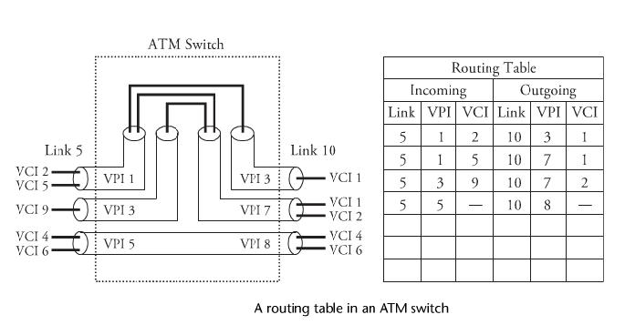
12. Below figure shows a routing table in an ATM switch, with routing
information for all active connections passing through the switch. The
routing information consists of the new VPI/VCI and new outgoing link for
every incoming VC. Link5, with VPIs 1, 3, and 5, can be switched on link
10 with VPIs 3, 7, and 8 through the ATM switch. A routing table provides
the detail of the switching function. For example, a cell with VPI 3 and VCI
9 on link 5 is set to be forwarded with VPI7 and VCI2 on link 10.
13. The ATM protocol structure in OSI model consist as a tightly linked layer consist of the physical layer, the ATM layer, the ATM adaptation layer (AAL), and higher layers. The physical layer includes two sublayers: the physical medium and transmission convergence. The physical medium sublayer defines the physical and electrical/optical interfaces with the transmission media on both the transmitter and the receiver.
14. The layer also
provides timing information and lin ecoding. The
transmission convergence sub layer provides frame adaptation and frame
generation/recovery.
transmission convergence sub layer provides frame adaptation and frame
generation/recovery.
15. The ATM layer provides services, including cell
multiplexing and
demultiplexing, generic flow control, header cell check generation and
extraction, and remapping of VPIs and VCIs. The AAL layer maps higher-
layer service data units, which are fragmented into fixed-size cells to be
delivered over the ATM interface.This layer collects and reassembles ATM
cells into service data units for transporting to higher layers.
More to come about other technologies.. Keep Watching